
Clicking on any of the images on this page will load the full size image.
I planned this model in detail, as shown in the following plan and elevations, although naturally some changes arose during construction!
In the elevations, shaded areas indicate the buttresses, hatched areas are roofs, while in the South elevation there is an area marked with crosses that represents the timber support for the roof over the entrance porch. The heights of features and between features are shown as numbers of courses. These elevation plans are closely matched by the Church as it was built. One little difference is that although I had planned for the roofs to overhang the walls a little I had not drawn the overhangs correctly beside the tower in the North and South elevations.
The ground plan includes six pillars in the interior, intended to support the upper level of the building, with dotted lines marking where beams would be placed for this upper level to be built on. As detailed below, a different approach was used, and in particular the pillars were abandoned.
I wanted tall stained-glass windows on the lower level and a big stained-glass feature window behind where the altar would be in the chancel. This meant the windows not matching the standard Brickplayer sizes, so I spent some time searching online for a suitable source. Eventually, I found a supplier on Etsy who would 3D-print windows to my specification. In my specifications, I didn't get everything right. First, in converting numbers of courses to metric heights, I rounded down a little. I didn't want them to be too big, but the result was that I often had to reduce the height of the top course of bricks to match the height of the window. So I did quite a bit of sandpapering!
Second, I concentrated on the height and width and forgot about the depth. Brickplayer windows have substantial side flanges to be glued to the surrounding brickwork, but when my windows arrived they were quite thin. They also lacked sills. My mistake, but not a serious one.
The same supplier on Etsy made the doors for me.
To put the stained-glass into the windows, I searched online for images of stained-glass church windows, downloaded the ones I liked, edited them to the right size, then printed them onto acetate sheets. These sheets are still sold as overhead transparency sheets, even though overhead projectors are now more or less redundant. Then, cut out, they were glued into the backs of the windows.
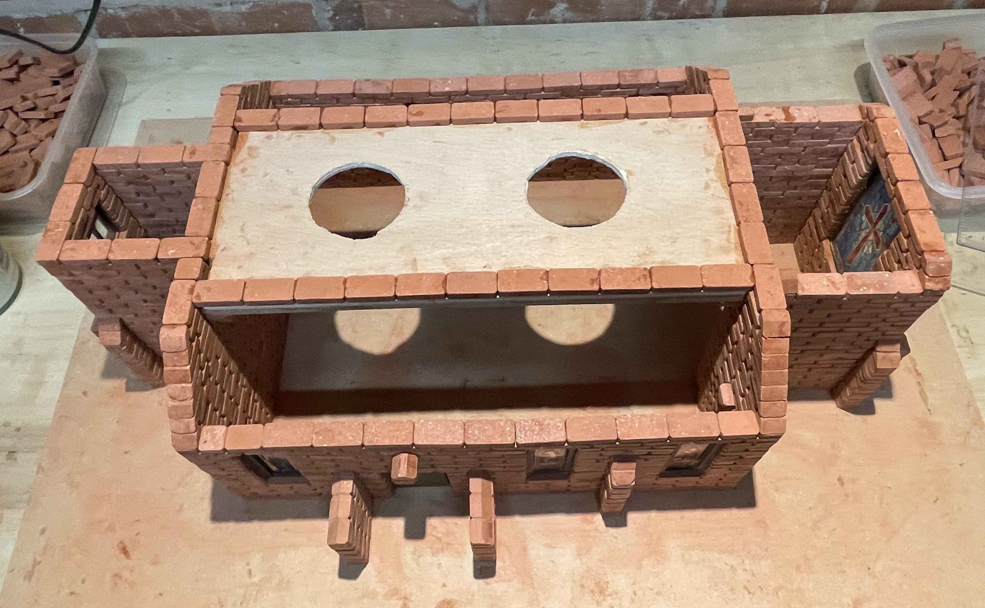
The above image shows a fairly early stage of construction. The first level's windows are in and the pillars in the middle of the nave have been built up 10 courses. However, the pillars were not stable. If any imperfection meant a course was not entirely flat then the next course did not glue on firmly, so the pillars were inclined to topple. It was also very difficult to keep them rising perpendicularly. So it was at about this point that they were abandoned and removed altogether.
The next two images show the alternative approach to supporting the upper level. First, beams were placed across. The Brickplayer beams are quite substantial, but just as I originally planned to use pillars because I was not happy to trust them to span this distance, the alternative involved gluing another platform on top to increase rigidity. The platform was made from 5.5mm plywood, which is the same thickness as the beams and equal to the height of one course of bricks.
The holes in the platform were cut because I wanted to have lighting inside the Church to show off the stained-glass. I planned to use tea-lights, and the holes would allow a couple of tea-lights to be dropped through to light the lower level (and to be lifted out again to turn them off). In fact, as we will see later on this page, the plan changed again!
These images illustrate some more little features of the build. The use of gable bricks is particularly noticeable. They create sloping tops for the buttresses and also the sloping wall sides for roofing.
To make the sloping tops of buttresses requires two gable bricks, one on top of the other. The first one is a half-brick B5, butting against the wall, but then I had to use a whole-brick B4, which projects out a little the other side of the wall. If you look carefully at the left-hand image you can see a couple of these internal projections. Where two buttresses meet at right angles, as for instance on the corners of the tower, it is necessary instead for one buttress to be one course higher than the other.
The finished Church is to have a gable roof over the nave, another over the chancel and a third over the porch. Over the sides of the nave at the lower level will be two sloping roofs. Apart from the gable over the nave, which will be simply laid on the walls so that it can be lifted off to attend to the lighting, all the roofs will be glued down. To assist with this for the gable over the porch, gable bricks B5 are used on the tops of the side walls, and an apex brick B6 projects from the main wall where the apex of the gable will be.
Notice also that a solid wall is made between the nave and the tower, so that lighting in the nave will not show through the windows in the tower.
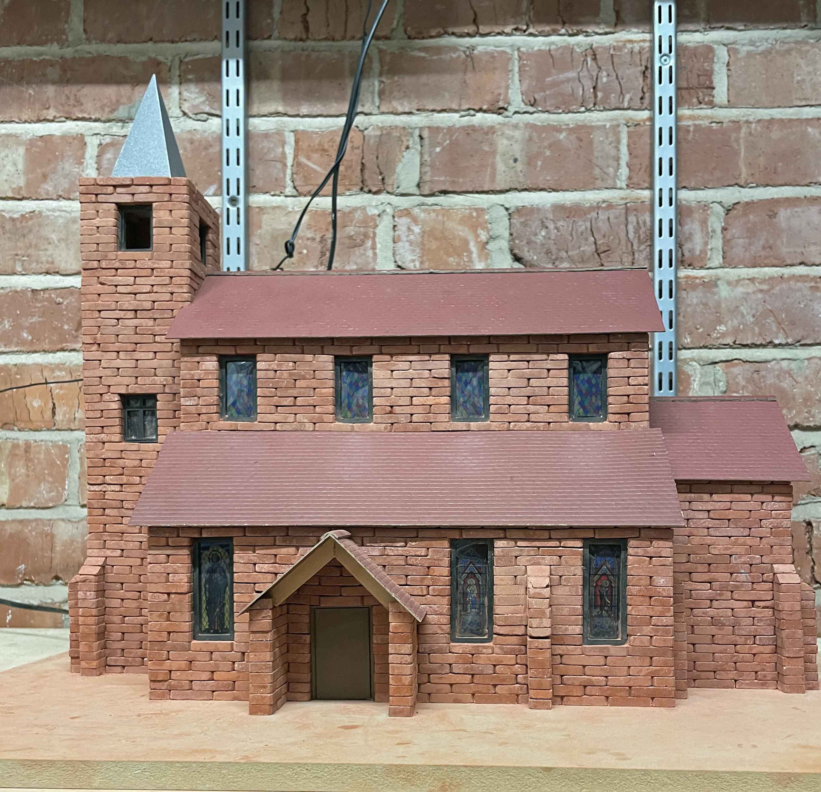
The next two images show the building almost finished, lacking only the upper part of the tower and the roofs, and then the finished building awaiting some landscaping.
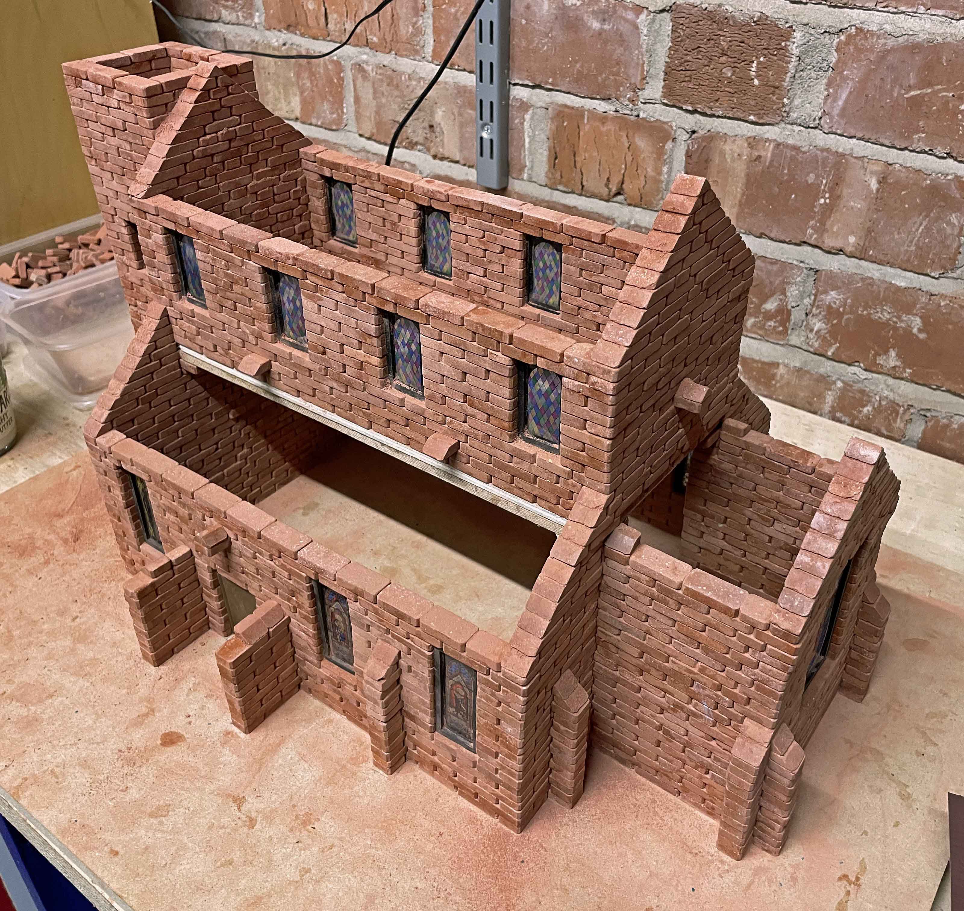
The left-hand image shows some more projecting gable and apex bricks to assist with gluing down the roofs. Notice also that one B5 gable brick has been removed from each of the porch walls (compare with the pictures of the platform build above). The explanation for this will be found in the discussion of the porch roof beams below. The finished building shown on the right above required two more technical challenges to be met.
The image below shows how I drew out a shape for the four triangles joined together. It was a straightforward exercise in school-level geometry!
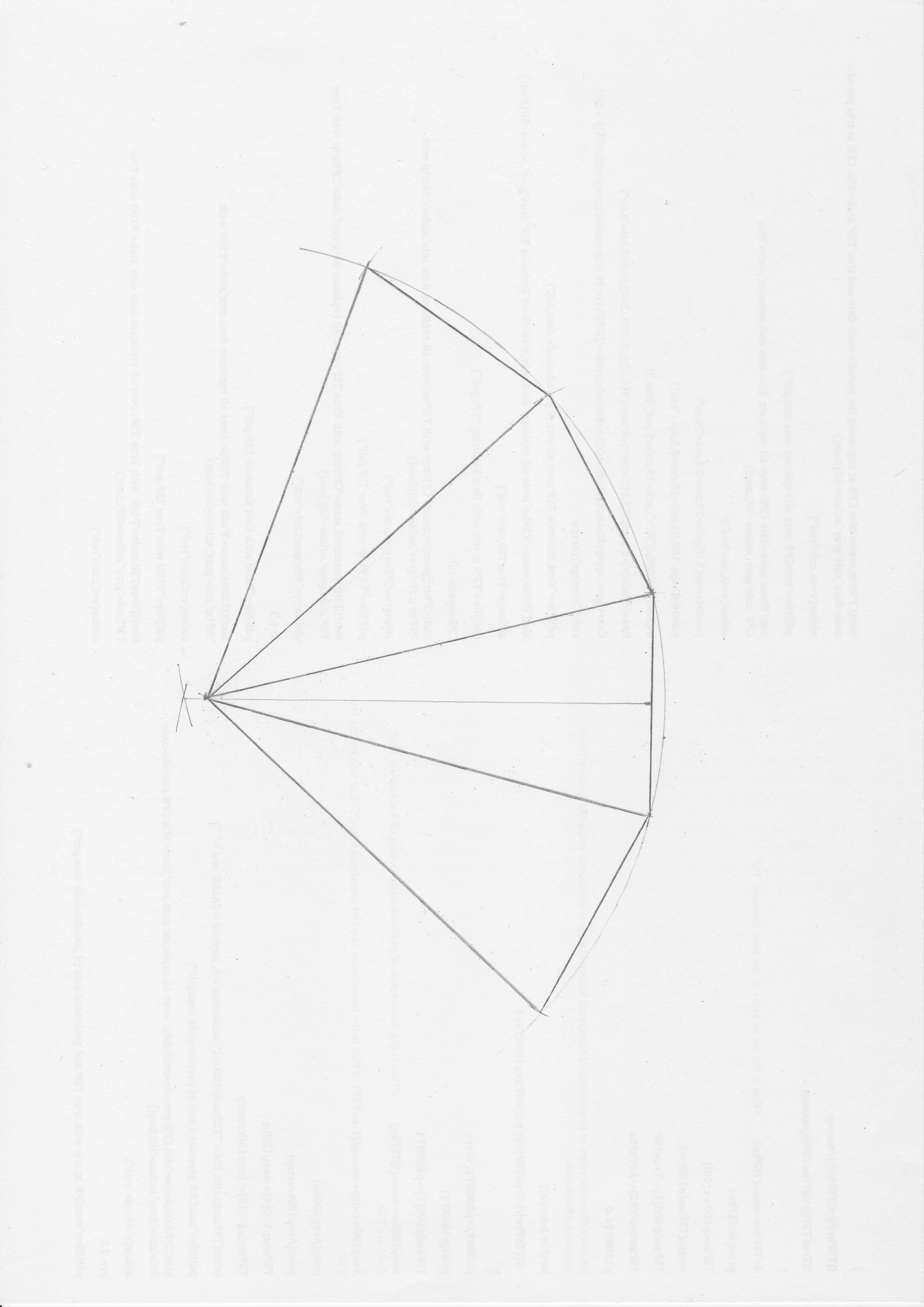
To see the detail, click on the image or the text below it. I first drew the vertical line of length 2" then constructed the perpendicular bisector (using the classical construction with compasses). Measuring length d = 4⅛" along that perpendicular bisector locates the vertex of the first triangle, and where the four triangles meet. Using the compasses again, I drew an arc centred at this vertex point and passing through the ends of the 2" line, then measured lengths of 2" to locate the three other base edges.
Having cut this shape out from the tarmac-effect sheet, scoring part-way through the lines joining the four triangles allowed it to be folded into the finished spire shape. Tape was used to join it up. The spire then just sits inside the tower on internally projecting bricks just one course below the top.
The second technical challenge was posed by the need to support the front of the gable roof over the porch. The roof beams (seen in the image of the completed building above) are made from lengths of Brickplayer soffit, which is thinner and narrower than the Brickplayer beams. In particular, the width is ⅜", as opposed to the ½" of a Brickplayer beam.
The image below shows the front elevation of the porch with two beams supporting the roof and joined together in the apex. Below that is an enlarged diagram of one roof beam (this one is under the roof section from A to B in the elevation diagram, while the other beam is a mirror image of this one).
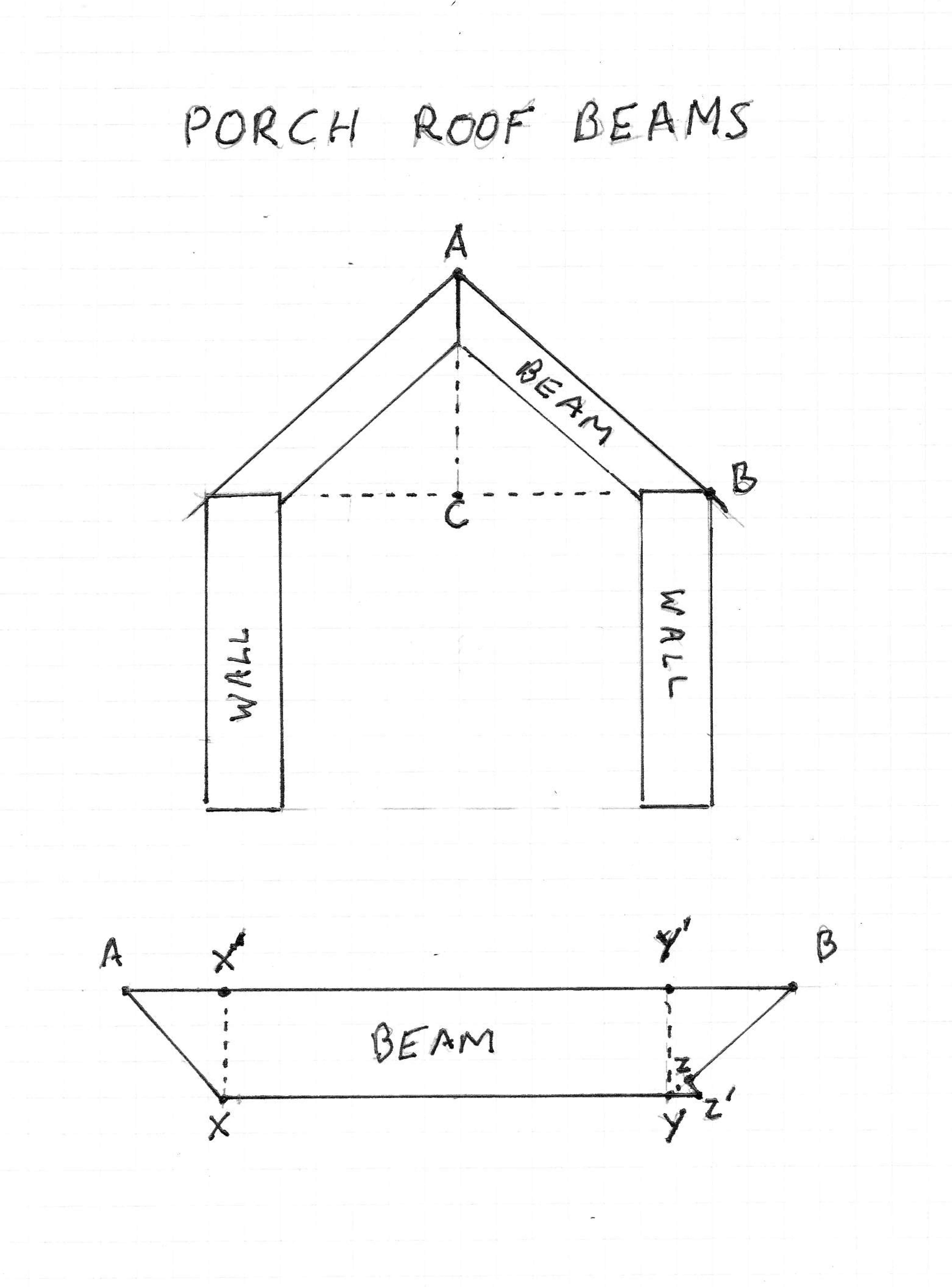
Dimensions are calculated as follows. First, looking at the elevation diagram, the distance from B to C is 1.75". The Standard Brickplayer gable bricks create a pitch that rises one course per quarter-inch, and given that one course is 7/32" high, this means that the distance from C to A is ⅞ times that from C to B, i.e. 1.53", and by Pythagoras we get the distance from A to B as 2.325".
Moving to the lower diagram, the top surface of the beam is A to B, measuring 2.325". The beam/soffit is ⅜" wide, so this is the distance from X to X' and from Y to Y'. Using again the fact that the pitch rises ⅞" per horizontal inch, the distance from A to X' is ⅞ of that from X to X', and hence is 0.33", while that from Y' to B is ⅜" divided by ⅞, i.e. 0.43". Using Pythagorus again, the distance from A to X is found to be 0.5", and that from B to Y is 0.57". Now this end of the beam sits over the wall, which has a width of 0.5", and we can take advantage of the extra 0.07" to create a little wedge. The point Z is distance 0.5" from B, and the triangle YZZ' will sit over the side of the wall to give a little more stability.
The beams sit a little back from the fronts of the walls. I cut a little off the B5 brick at the front of each wall, equal to the width of the beam/soffit, so that the beams sit behind these bricks and are glued to them and to the B5 bricks behind them. (In the left-hand image of the final stages of the build, above, these front B5 bricks have been removed in preparation for being cut.)
Simulated grass was applied first, of course. The driveway to the side door is cut from the tarmac-effect sheets again. The gravel path to the porch is made from a reddish-coloured grit. And the final results can be seen at the top of this page.
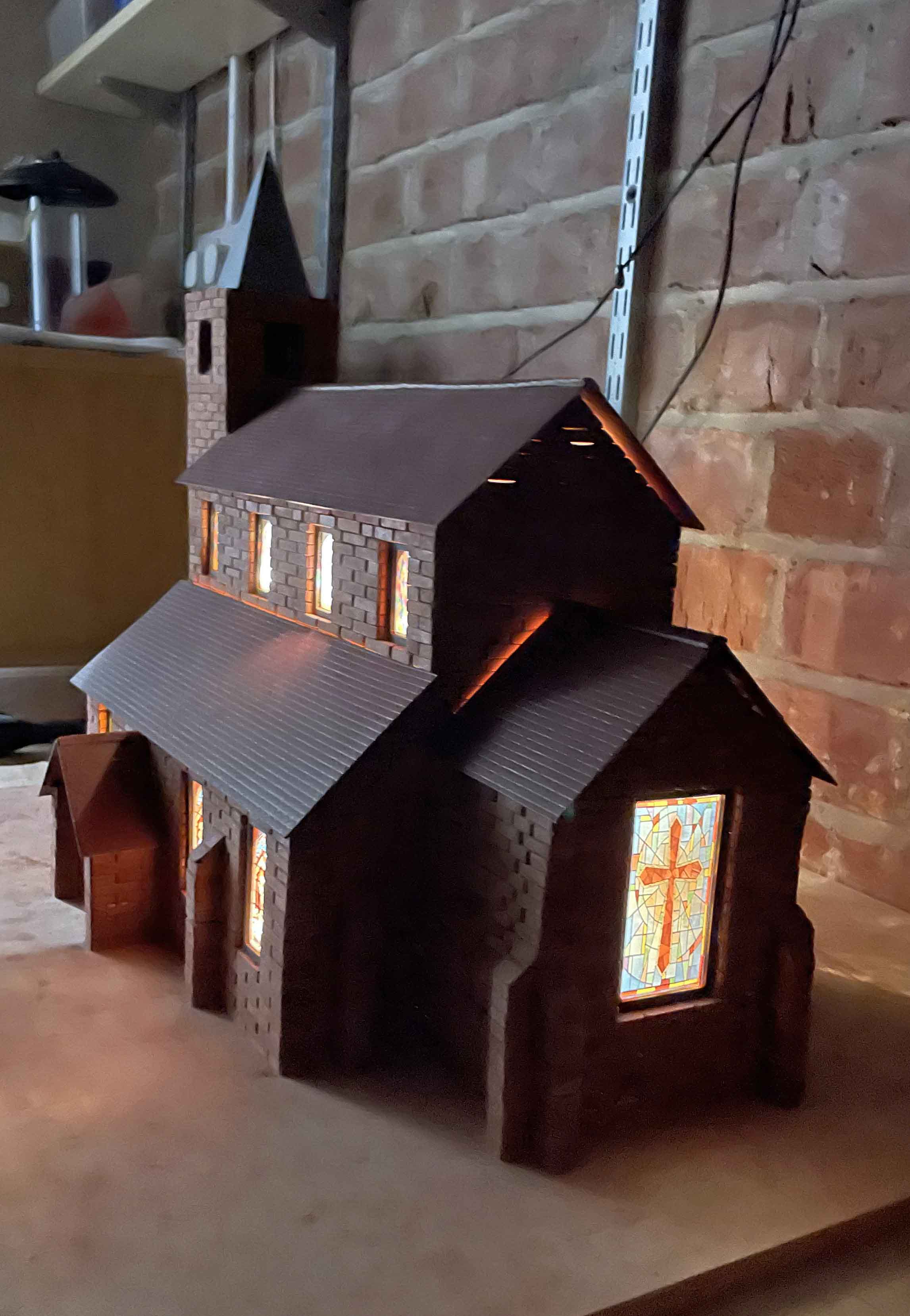
My third Brickplayer project was now complete, and the one remaining challenge was to find a home for yet another large and heavy model!
More links: This Brickplayer website sits within my personal website tonyohagan.co.uk. The links below provide access to the other parts of my website.

|

|

|

|

|

|